显微测量系统
Vic-3D Micro Microscopy
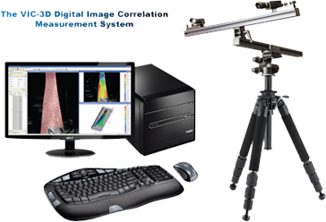
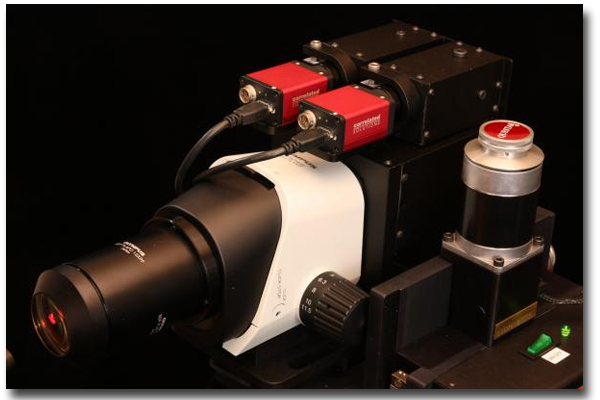
Correlated Solutions, Inc.出品的Vic-3D Micro系统是Vic-3D系列测量解决方案产品线的新成员。 Vic-3D Micro可在高放大倍数下实现精确的位移和应变测量。
技术背景 Background
由于三维数字图像相关技术(DIC)具有出色的准确性、稳健性和易用性,因此已广泛应用于应变测量。但是,对于需要高放大倍数的样品,3D测量仍很难获得。这主要是由于缺乏具有足够景深的光学元件以从不同视角获取3D分析所需的两张高放大率图像。
Three-dimensional digital image correlation (DIC) has found widespread popularity for strain measurements due to its excellent accuracy, robustness and ease of use. However, 3D measurements have been difficult to obtain on specimens where high magnification is required. This is mainly due to the lack of optics with sufficient depth-of-field to acquire two high magnification images from different viewing angles.
立体显微镜克服了这些景深限制。然而,立体显微镜的内部结构妨碍了使用传统模型(例如Seidel镜头失真)对图像失真进行适当校正。这些未经校正的图像将导致形貌和应变测量产生严重的偏差。事实上,观察中数千微应变的偏差量级并不鲜见。
Stereo microscopes overcome these depth-of-field limitations. However, the internal construction of stereo microscopes prevents proper correction of image distortions using traditional models, such as Seidel lens distortions. These uncorrected images will result in severely biased shape and strain measurements. In fact, it is not uncommon to observe bias levels of several thousand microstrain.
为了克服这个问题,CSI公司开发了一种易于使用的标定方法,该方法不会遇到与传统参数失真模型相关的问题。 该标定方法计算立体显微镜的非参数畸变场,并已被证实可完全消除测量中的形貌和应变偏差。
To overcome this problem, Correlated Solutions, Inc., has developed an easy-to-use calibration method that does not suffer from the problems associated with traditional parametric distortion models. The calibration method computes the non-parametric distortion fields of the stereo microscope and has been shown to completely eliminate shape and strain bias from the measurements.
系统特性 System Features
- 视场范围(变焦范围):0.8mm-7mm
- 三维坐标,位移,速度和完整应变张量的全场测量
- 自动标定
- 图像匹配可以通过简单的调整自动重叠
-
强大的数据可视化工具
- 数据云图显示可以覆盖在测试样本的图像上
- 根据用户定义的线条和圆圈从3D图中提取数据
- 用于统计分析、应力 - 应变曲线等数据的后处理工具
-
使用FLEXPortTM数据工具方便地输出数据
- 数据可以以Tecplot /纯ASCII,Matlab和STL格式输出
- 节点数据可以轻松提取用于FEA验证
-
一年的技术支持和软件升级
- 7*24小时提供实时技术支持
- 同时提供现场支持和咨询
- 所有部件材料和/或制造缺陷的一年更换保修
- Field of view (zoom range): 0.8mm-7mm
- Full-field measurements of 3D coordinates, displacements, velocities, and complete strain tensors
- Automatic calibration
- Image pairs can be automatically overlapped with a simple adjustment
-
Powerful tools for visualizing data
- Contour displays which can be overlaid onto images of the test specimen
- Data extraction from 3D plots based on user defined lines and circles
- Post-processing tools for statistical analysis, stress-strain curves, and more
-
Convenient exporting of data with the FLEXPortTM data tool
- Data can be exported in Tecplot/plain ASCII, Matlab, and STL formats
- Node data can be easily extracted for FEA validation
-
One year of technical support and software upgrades
- Live technical support is available 7*24 H
- On-site support and consulting is also available
- One-year replacement warranty for defects in materials and/or workmanship on all parts.

